| Concept: Structured Class |
 |
|
| Related Elements |
|---|
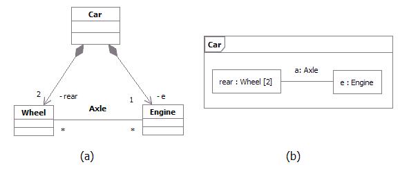
DefinitionAccording to UML ([UML04]), a Class is a subtype of both EncapsulatedClassifier and metaclass Class, which brings to a Class the capability to have an internal structure and ports. Also, a component is defined by UML as a subtype of Class. Therefore, within RUP context, we refer to both components and classes as being structured classes. PartAn instance of a structured class contains an object or set of objects corresponding to each part. All such instances are destroyed when the containing structured class instance is destroyed. The example below shows two possible views of the Car class:
Example: Parts playing their roles inside a structured class ConnectorA connector is an instance of relationship between two parts in a structured class. It is a link to allow communication. Connectors may be implemented by ordinary associations or by transient relationships, such as procedure parameters, variables, global values, or other mechanisms. The internal "wiring" of a structured class is specified with assembly connectors and delegation connectors:
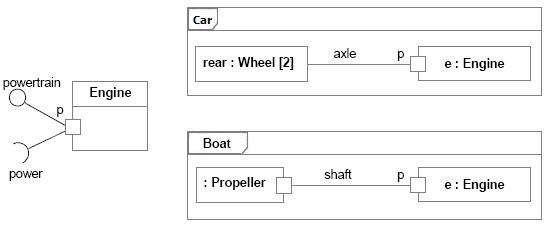
PortA port is a structural feature of a structured class. Encapsulation can be increased by forcing communications from outside the structured class to pass through ports obeying declared interfaces, which brings additional precision in specification and interconnection for that structured class. The required and provided interfaces of a port specify everything that is necessary for interactions through that interaction point. If all interactions of a structured class with its environment are achieved through ports, then the internals of the structured class are fully isolated from the environment. This allows such a structured class to be used in any context that satisfies the constraints specified by its ports. There is no assumption about how a port is implemented. It might be implemented as an explicit object, or it might be merely a virtual concept that does not explicitly appear in the implementation. Examples of ports are provided below: Example 1
Port of an Engine being used by a Car and a Boat The figure above shows a class Engine with a port p and two interfaces:
At port p, the Engine class is completely encapsulated; it can be specified without
any knowledge of the environment the engine will be embedded in. As long as the environment obeys the constraints
expressed by the provided and required interfaces of the engine, the engine will function properly.
As long as the interaction between the Engine and the part linked to its port p obeys the constraints specified by the provided and required interfaces, the engine will function as specified, whether it is an engine of a car or an engine of a boat. Furthermore, even if Engine had other declared ports, such as a port f for Fuel Consumption, the wheels of a car and the propeller of a boat would still access the Engine through port p. Port f would be of interest of a fuel meter, regardless of what kind of fuel is being used and what kind of fuel meter cars and boats might have. Example 2This example of ports is based on Java Logging API ([JAV03]), which is a package that provides the following classes and interfaces of the Java 2 platform's core logging facilities, among others:
Those classes and interfaces are involved in two important kinds of collaborations. Some classes and interfaces are used to write to the log while others are used to administrate the log. The figure below shows two different collaborations that clients and administrators have with the log, modeled as UML collaborations:
Different collaborations that clients and administrators have with the log One possible UML 2.0 representation to model the logging services and its collaborations would be using a component with ports and declared interfaces, as shown in the figure below:
Java Logging API package being implemented as a component with provided interfaces grouped into ports In the Java Logging API specification, some of the logging services were implemented as classes and others as interfaces. In this example, we model each of those services as provided interfaces, which could be realized by parts inside the component. The two different kinds of behavior related to Writing and Administration collaborations mentioned above could be represented by interfaces logically grouped into ports. Therefore, we have:
This modeling alternative brings a separation of concerns, by logically grouping interfaces into different ports. We have additional precision for the component specification and the interconnection it can have with the external world. ModelingDuring design, classes and components may be decomposed into collections of connected parts that may be further decomposed in turn. A composite structure diagram can be used to show the decomposition of a structured class. As an example, the figure below shows a composite structure diagram for the box office in the ticketing system. This class is decomposed into three parts:
Each part interacts through a well-defined interface specified by its ports. The entire box office interacts with the outside through a port. Messages on this port are dispatched to the ticket seller class, but the internal structure of the box office class is hidden from outside clients.
Example: Composite structure diagram for a ticketing system. UML 1.x RepresentationNote that Structured Class is a new concept in UML 2.0. Much of what RUP defines as Capsule can be represented using Structured Class as notation (see Artifact: Capsule and Guideline: Capsule for more information on this topic).If your tool supports only UML 1.5, an alternative representation is also discussed in Artifact: Capsule and Guideline: Capsule.
Refer to Differences Between UML 1.x and UML 2.0 for more information. |
© Copyright IBM Corp. 1987, 2006. All Rights Reserved. |