| Guideline: Capsule |
 |
|
| Related Elements |
|---|
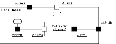
TopicsPortsBecause ports are on the boundary of a capsule, they may be visible both from outside the capsule and inside. When viewed from the outside, all ports present the same impenetrable object interface and cannot be differentiated except by their identity and the role that they play in their protocol. However, when viewed from within the capsule, we find that ports can be one of two kinds: relay ports and end ports. They differ in their internal connections - relay ports are connected to sub-capsules while end ports are connected to the capsule's state machine. Generally speaking, relay ports serve to selectively export the "interfaces" of internal sub-capsules while end ports are boundary objects for the state machine of a capsule. Both relay and end ports may appear on the boundary of the capsule and, as noted, are indistinguishable from the outside. Relay PortsRelay ports are ports that simply pass all signals through. They provide an "opening" in the encapsulation shell of a capsule that can be used by its sub-capsules to communicate with the outside world without actually being exposed to the outside world (and vice versa). A relay port is connected, through a connector, to a sub-capsule and is normally also connected from outside to some other "peer" capsule. They receive signals coming from either side and simply relay it to the other side keeping the direction of signal flow. This is achieved without delay or loss of information unless there is no connector attached on the other side. In the latter case, the signal is lost. Relay ports allow the direct (zero overhead) delegation of signals destined for a capsule to a sub-capsule without requiring intervention by the state machine of the capsule. Relay ports can only appear on the boundary of a capsule and, consequently, always have public visibility. End PortsTo be useful, a chain of connectors must ultimately terminate in an end port that communicates with a state machine. End ports are boundary objects for the state machines of capsules (although, as we shall see, some of them also serve as boundary objects for capsules as well). End ports are the ultimate sources and sinks of all signals sent by capsules. These signals are generated by the state machines of capsules. To send a signal, a state machine invokes a send or call operation on one of its end ports. The signal is then relayed through the attached connector, possibly passing through one or more relay ports and chained connectors, until it finally encounters another end port, usually in a different capsule. Since signal-based communication can be asynchronous, an end port has a queue to hold messages that have been received but not yet processed by the state machine (i.e., it acts as a mailbox). The reception of the signal and the dispatching of the receiving state machine is performed by the state machine according to standard UML semantics. Like relay ports, end ports may appear on the boundary of a capsule with public visibility. These ports are called public end ports. Such ports are boundary objects of both the state machine and the containing capsule. However, end ports may also appear completely inside the capsule as part of its internal implementation structure. These ports are used by the state machine to communicate with its sub-capsules or with external implementation-support layers. These internal end ports are called protected end ports since they have protected visibility. Note that the kind of port is totally determined by its internal connectivity and its visibility outside the capsule; the various terms (relay port, public end port, private end port) are merely shorthand terminology. A public port that is not connected internally may become either a relay port or an end port depending on how it is later connected, or it may remain unconnected and be a sink for incoming signals. Port VisibilityFrom an external viewpoint, a port is a port; it is not possible or even desirable to determine whether a port is a relay port or an end port. However, when the decomposition of a capsule is shown, we can see inside the capsule and the end port/relay port distinction is indicated graphically as shown below.
Port notation - communication diagram (internal view) Port-Based TriggersIn practice, it often happens that two or more ports of the same capsule use the same protocol but are semantically distinct. Also, the same signal may appear in more than one protocol role supported by different ports of a capsule. In either case, it may be necessary to distinguish the specific end port that received the current signal. That allows applications to handle the same signal differently depending on the source of that signal as well as the state. We refer to this type of trigger as a port-based trigger. Port-based triggers are modeled in UML by using guard conditions that checks for a particular source port. State MachinesThe specification for the state machine part of a capsule as well as the specification of valid protocol sequences is done using standard UML state machines. Time ServiceAs can be expected, in most real-time systems time is a first-order concern. In general, two forms of time-based situations need to be modeled: the ability to trigger tasks at a particular time of day and, the ability to trigger tasks after a certain interval has expired from a given point in time. Most real-time systems require an explicit and directly accessible (controllable) timing facility - a time service. This service, which can be accessed through a standard port (service access point), converts time into events that can then be handled in the same way as other signal-based events. For example, with such a service, a state machine can request that it be notified with a "timeout" event when a particular time of day has been reached or when a particular interval has expired. Capsule TaxonomyCapsules as a concept may be used in a number of different ways. To reflect this, a capsule hierarchy and taxonomy can be described to cover the common usages of capsules.
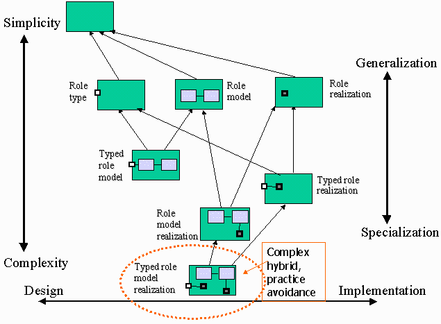
Capsule Taxonomy showing generalization hierarchy The basic capsule taxonomy is:
There are three useful hybrids of these basic types, which represent mixtures of the basic definitions:
The remaining capsule type, the 'typed role model realization', which defines structure and interface, plus behavior in the abstract (for the interface) and in the specific (for the internal structure) is complex and can be hard to understand, let alone implement correctly. It is mentioned for the sake of the case where unit tests on the capsule need to be defined as part of the capsule itself, hence the two separate state machines. In most cases, this construct is best avoided. UML 2.0 RepresentationNote that the current RUP representation for Capsules is based on UML 1.5 notation. Much of this can be represented in UML 2.0 using the Concept: Structured Class.
Refer to Differences Between UML 1.x and UML 2.0 for more information. |
© Copyright IBM Corp. 1987, 2006. All Rights Reserved. |

