| Guideline: Include-Relationship |
 |
|
| Related Elements |
|---|
ExplanationThe include-relationship connects a base use case to an inclusion use case. The inclusion use case is always abstract. It describes a behavior segment that is inserted into a use-case instance that is executing the base use case. The base use case has control of the relationship to the inclusion and can depend on the result of performing the inclusion, but neither the base nor the inclusion may access each other's attributes. The inclusion is in this sense encapsulated, and represents behavior that can be reused in different base use cases. You can use the include-relationship to:
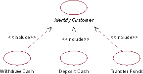
Example: In an ATM system, the use cases Withdraw Cash, Deposit Cash, and Transfer Funds all need to include how the customer is identified to the system. This behavior can be extracted to a new inclusion use case called Identify Customer, which the three base use cases include. The base use cases are independent of the method used for identification, and it is therefore encapsulated in the inclusion use case. From the perspective of the base use cases, it does not matter whether the method for identification is to read a magnetic bank card, or perform a retinal scan. They only depend on the result of Identify Customer, which is the identity of the customer. And vice versa, from the perspective of the Identify Customer use case, it does not matter how the base use cases use the customer identity or what has happened in them before the inclusion is executed - the method for identification is still exactly the same.
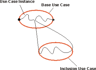
In the ATM system, the use cases Withdraw Cash, Deposit Cash, and Transfer Funds all include the use case Identify Customer. A base use case may have multiple inclusions. One inclusion use case may be included in several base use cases. This does not indicate any relationship between the base use cases. You may even have multiple include-relationships between the same inclusion use case and base use case, provided the inclusion is inserted at different locations of the base use case. The include-relationship defines what the location is. All additions may be nested, which means that an inclusion use case may serve as the base use case for another inclusion. Since the inclusion use case is abstract, it does not need to have an actor associated with it. A communication-association to an actor is only needed if the behavior in the inclusion explicitly involves interaction with an actor. Executing the InclusionThe behavior of the inclusion is inserted in one location in the base use case. When a use-case instance following the description of a base use case reaches a location in the base use case from which include-relationship is defined, it will follow the description of the inclusion use case instead. Once the inclusion is performed, the use-case instance will resume where it left off in the base use case.
A use-case instance following the description of a base use case including its inclusion. The include-relationship is not conditional: if the use-case instance reaches the location in the base use case for which it is defined, it is always executed. If you want to express a condition, you need to do that as part of the base use case. If the use-case instance never reaches the location for which the include-relationship is defined, it will not be executed.
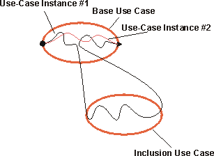
Use-case instance #1 reaches the location in the base use case for which the include-relationship is defined, and the inclusion is performed. Use-case instance #2 does not reach that location, and the inclusion is therefore not performed as part of that instance. The inclusion use case is one continuous segment of behavior, all of which is included at one location in the base use case. If you have separate segments of behavior that need to be inserted at different locations, you should consider the extend-relationship (see Guideline: Extend-Relationship) or the use-case-generalization (see Work Product Guideline: Use-Case-Generalization) instead. Describing the Include-RelationshipFor the include-relationship, you should define the location within in the behavior sequence of the base use case where the inclusion is to be inserted. The location can be defined by referring to a particular step or subflow within the flow of events of the base use case. Example: In the ATM system, the use case Withdraw Cash includes the use case Identify Customer. The include-relationship from Withdraw Cash to Identify Customer can be described as follows: Identify Customer is inserted between sections 1.1 Start of Use Case and 1.2 Ask for Amount in the flow of events of Withdraw Cash. For the sake of clarity, you should also mention the inclusion in the text describing the flow of events of the base use case. Example of UseIf there is a behavior segment in a use case where you can see that the use case is not dependent on how things are done, but it is dependent on the result of the function, you can simplify the use case by extracting this behavior to an inclusion use case. The inclusion use case can be included in several base use cases, which means it lets you reuse behavior among use cases in the model. Consider the following step-by-step outlines to use cases for a simple phone system: Place Call
Start System
The text listed in blue is very similar; in both cases we are performing the same behavior, although for very different reasons. This similarity can be exploited, and we can extract the common behavior into a new use case, Manage Virtual Circuits. Once common behavior has been extracted, the use cases become: Place Call
Start System
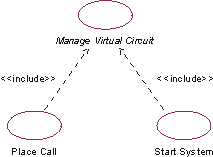
In a use-case diagram, the include-relationship that is created will be illustrated as follows:
The use cases Place Call and Start System both include the behavior of the abstract use case Manage Virtual Circuit. |
© Copyright IBM Corp. 1987, 2006. All Rights Reserved. |