Task: Subsystem Design
This task describes how to document Subsystem elements and their behavior as well as Subsystem dependencies.
Disciplines: Analysis & Design
Purpose
  • To define the behaviors specified in the subsystem's interfaces in terms of collaborations of contained design elements and external subsystems/interfaces.
  • To document the internal structure of the subsystem.
  • To define realizations between the subsystem's interfaces and contained classes.
  • To determine the dependencies upon other subsystems
Relationships
Main Description

 UML 1.x Representation

The same considerations about subsystemdependencies apply if UML 1.5 notation is being used:


Diagram described in accompanying text.

Example of Subsystem Layering using direct dependencies

Diagram described in accompanying text.

Example of Subsystem Layering using Interface dependencies

Refer to Differences Between UML 1.x and UML 2.0 for more information.

Steps
Distribute Subsystem Behavior to Subsystem Elements
Purpose To specify the internal behavior of the subsystem.
To identify new design classes or design subsystems needed to satisfy subsystem behavioral requirements. 

The external behavior of a subsystem is primarily defined by the interfaces it realizes. When a subsystem realizes an interface, it makes a commitment to support each and every operation defined by the interface. The operation may be in turn realized by an operation on a design element (i.e., Design Class or Design Subsystem) contained by the subsystem; this operation may require collaboration with other design elements

The collaborations of model elements within the subsystem should be documented using sequence diagrams which show how the subsystem behavior is realized. Each operation on an interface realized by the subsystem should have one or more documenting sequence diagrams. This diagram is owned by the subsystem, and is used to design the internal behavior of the subsystem.

If the behavior of the subsystem is highly state-dependent and represents one or more threads of control, state machines are typically more useful in describing the behavior of the subsystem. State machines in this context are typically used in conjunction with active classes to represent a decomposition of the threads of control of the system (or subsystem in this case), and are described in statechart diagrams, see Guideline: Statechart Diagram. In real-time systems, the behavior of Artifact: Capsules will also be described using state machines.Within the subsystem, there may be independent threads of execution, represented by active classes.

In real-time systems, Artifact: Capsules will be used to encapsulate these threads.

Example:

The collaboration of subsystems to perform some required behavior of the system can be expressed using sequence diagrams:

Diagram described in accompanying text.

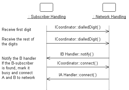
This diagram shows how the interfaces of the subsystems are used to perform a scenario. Specifically, for the Network Handling subsystem, we see the specific interfaces (ICoordinator in this case) and operations the subsystem must support. We also see the NetworkHandling subsystems is dependent on the IBHandler and IAHandler interfaces.

Looking inside the Subsystem, we see how the ICoordinator interface is realized:

Diagram described in accompanying text.

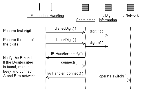
The Coordinator class acts as a "proxy" for the ICoordinator interface, handling the interface operations and coordinating the interface behavior.

This "internal" sequence diagram shows exactly what classes provide the interface, what needs to happen internally to provide the subsystem's functionality, and which classes send messages out from the subsystem. The diagram clarifies the internal design, and is essential for subsystems with complex internal designs. It also enables the subsystem behavior to be easily understood, hopefully rendering it reusable across contexts.

Creating these "interface realization" diagrams, it may be necessary to create new classes and subsystems to perform the required behavior. The process is similar to that defined in Use Case Analysis, but instead of Use Cases we are working with interface operations. For each interface operation, identify the classes (or in some cases where the required behavior is complex, a contained subsystem) within the current subsystem which are needed to perform the operation. Create new classes/subsystems where existing classes/subsystems cannot provide the required behavior (but try to reuse first).

Creation of new design elements should force reconsideration of subsystem content and boundary. Be careful to avoid having effectively the same class in two different subsystems. Existence of such a class implies that the subsystem boundaries may not be well-drawn. Periodically revisit Task: Identify Design Elements to re-balance subsystem responsibilities.

It is sometimes useful to create two separate internal models of the subsystem - a specification targeted to the subsystem client and a realization targeted to the implementers. The specification may include "ideal" classes and collaborations to describe the behavior of the subsystem in terms of ideal classes and collaborations. The realization, on the other hand, corresponds more closely to the implementation, and may evolve to become the implementation.  For more information on Design Subsystem specification and realization, see Work Product Guideline: Design Subsystem, Subsystem Specification and Realization.

Document Subsystem Elements
Purpose To document the internal structure of the subsystem. 

To document the internal structure of the subsystem, create one or more class diagrams showing the elements contained by the subsystem, and their associations with one another. One class diagram should be sufficient, but more can be used to reduce complexity and improve readability.

An example class diagram is shown below:

Diagram described in accompanying text.

Example Class Diagram for an Order-Entry System.

Modeled as a component, the internal content of a subsystem can be alternatively represented within the component rectangle in a component diagram. This representation also allows us to include the interaction points of this subsystem to other parts of the system, which is done through its interfaces.

An example of component diagram is shown below, depicting the Order subsystem, its internal content, as well as its provided and required interfaces.

Diagram described in accompanying text.

Example component diagram for Order Subsystem

As a component is a structured class, it can be tightly encapsulated by forcing communications from outside to pass through ports obeying declared interfaces, which brings additional precision in specification and interconnection for that component. This representation allows us to "wire" instances of parts through connectors to play a specific role in the component implementation (refer to Concept: Structured Class for additional information).

An example of composite structure diagram for the Order subsystem using interfaces and ports is shown below.

Diagram described in accompanying text.

Example composite structure diagram for Order Subsystem


In addition, a statechart diagram may be needed to document the possible states the subsystem can assume, see Guideline: Statechart Diagram.

The description of the classes contained in the subsystem itself is handled in the Task: Class Design.

Describe Subsystem Dependencies
Purpose To document the interfaces upon which the subsystem is dependent. 

When an element contained by a subsystem uses some behavior of an element contained by another subsystem, a dependency is created between the enclosing subsystems. To improve reuse and reduce maintenance dependencies, we want to express this in terms of a dependency on a particular Interface of the subsystem, not upon the subsystem itself nor on the element contained in the subsystem.

The reason for this is two-fold:

  • We want to be able to substitute one model element (including subsystems) for one another as long as they offer the same behavior. We specify the required behavior in terms of interfaces, so any behavioral requirements one model element has on another should be expressed in terms of interfaces.
  • We want to allow the designer total freedom in designing the internal behavior of the subsystem so long as it provides the correct external behavior. If a model element in one subsystem references a model element in another subsystem, the designer is no longer free to remove that model element or redistribute the behavior of that model element to other elements. As a result, the system is more brittle.

In creating dependencies, ensure that there are no direct dependencies or associations between model elements contained by the subsystem and model elements contained by other subsystems. Also ensure that there are no circular dependencies between subsystems and interfaces; a subsystem cannot both realize an interface and be dependent on it as well.

Dependencies between subsystems, and between subsystems and packages, can be drawn directly as shown below. When shown this way, the dependency states that one subsystem (Invoice Management, for example) is directly dependent on another subsystem (Payment Scheduling Management).


Diagram described in accompanying text.

Example of Subsystem Layering using direct dependencies

When there is a potential for substitution of one subsystem for another (where they have the same interfaces), the dependency can be drawn to an Interface realized by the subsystem, rather than to the subsystem itself. This allows any other model element (subsystem or class) which realizes the same interface to be used. Using interface dependencies allows flexible frameworks to be designed using replaceable design elements.


Diagram described in accompanying text.

Example of Subsystem Layering using Interface dependencies


More Information