|
Purpose
|
To document the interfaces upon which the subsystem is dependent.
|
When an element contained by a subsystem uses some behavior of an element contained by another subsystem, a dependency
is created between the enclosing subsystems. To improve reuse and reduce maintenance dependencies, we want to express
this in terms of a dependency on a particular Interface
of the subsystem, not upon the subsystem itself nor on the element contained in the subsystem.
The reason for this is two-fold:
-
We want to be able to substitute one model element (including subsystems) for one another as long as they offer the
same behavior. We specify the required behavior in terms of interfaces, so any behavioral requirements one model
element has on another should be expressed in terms of interfaces.
-
We want to allow the designer total freedom in designing the internal behavior of the subsystem so long as
it provides the correct external behavior. If a model element in one subsystem references a model element in
another subsystem, the designer is no longer free to remove that model element or redistribute the behavior of that
model element to other elements. As a result, the system is more brittle.
In creating dependencies, ensure that there are no direct dependencies or associations between model elements contained
by the subsystem and model elements contained by other subsystems. Also ensure that there are no circular dependencies
between subsystems and interfaces; a subsystem cannot both realize an interface and be dependent on it as well.
Dependencies between subsystems, and between subsystems and packages, can be drawn directly as shown below. When shown
this way, the dependency states that one subsystem (Invoice Management, for example) is directly dependent on another
subsystem (Payment Scheduling Management).
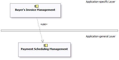
Example of Subsystem Layering using direct dependencies
When there is a potential for substitution of one subsystem for another (where they have the same interfaces), the
dependency can be drawn to an Interface realized by the subsystem, rather than to the subsystem
itself. This allows any other model element (subsystem or class) which realizes the same interface to be used. Using
interface dependencies allows flexible frameworks to be designed using replaceable design elements.
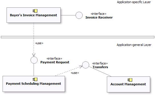
Example of Subsystem Layering using Interface dependencies
|
