In previous generations of store systems proprietary and low-capacity machines were used for the PoS terminals and there were restrictions on bandwidth in-store as well as out-of-store - these restrictions are largely now gone. With this in mind, and the existing move to service-oriented architecture within the enterprise back-end systems it has been decided that some of the capabilities provided by the ISS and central servers shall be exposed to the trading application as services.
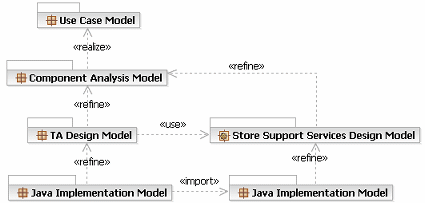
It is important to note that this project is to improve the technical implementation of currently existing functions and so does not include a great deal of time spent in either business modeling or analysis as we can reuse the models created for the original trading application. The current set of models (on the left in the diagram below) follow the structure shown below, showing a RUP Use Case Model, an Analysis Model for the common components of the trading application followed by the detailed Design Model and finally a set of Implementation Models for the Java development teams.
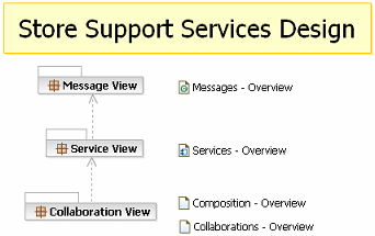
For more information see the tool mentor Creating a Service Model in RSA.
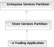
Also note that in the picture above the architect has introduced an additional element, the trading application itself, to allow for descriptions of communication between the application and the services. The trading application is a UML 2.0 component with the stereotype Service Consumer.
For more information see the concept Solution Partitioning.| Name | Technology | Inputs | Outputs | Comments |
|---|---|---|---|---|
| sp_get_custlist_by_phone | SQL Server Stored Procedure | phonenum (char 10) | List of:
custid (id) |
This stored procedure returns a list of customer details by phone number, the list may be presented to the customer for selection. The sp_get_cust_details call is used to return a single customer record. |
| sp_get_cust_details | SQL Server Stored Procedure | custid (id) | Customer record | The details of a customer are returned, their name, address, contact information and so on. |
| CUST_QUERY | IBM MQSeries | phonenum (char 10) return-queue-name (char 120) correlation-id (char 120) |
N/A | Into this queue the application places the details of the customers to query, the message is delivered to the center where the server posts the reply message to the identified return queue. |
| <return-queue-name> | IBM MQSeries | N/A | correlation-id (char 120) List of Customer record |
When returning the customer records the return message also contains the correlation-id to ensure that the reply can be associated with a given request. This allows the in-store server to have a single return queue for all terminals, the terminal queries the queue for a response message with its correlation id. |
| sp_get_invstate_for_sku | SQL Server Stored Procedure | sku (char 13) | Inventory record | |
| INVENTORY_QUERY | IBM MQSeries | sku (char 13) return-queue-name (char 120) correlation-id (char 120) |
N/A | |
| <return-queue-name> | IBM MQSeries | N/A | Inventory record |
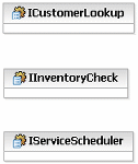
Next we analyze possible usage patterns for the services, for example we could actually have two services, one in-store and one enterprise, where the logic for the database access and enterprise access are both encapsulated in the in-store service. Alternatively we might choose to have a facade service in the store that encapsulates the logic and calls two identical services, one that encapsulates the local database access and the second at the enterprise. The second choice adds flexibility in changing the logic accessing the two stores, yet adds overhead and communication costs for a relatively simple function. So, for the customer lookup and the inventory lookup the first option has been chosen. As yet the details of the distribution of services and service providers are not decided, service identification is far more effective if focused only on service specifications.
To identify the roles and responsibilities of these services we use a Service Collaboration and specifically a UML 2.0 Composite Structure diagram representing the configuration of the services for customer lookup. The structure diagram is shown below and we can see UML 2.0 Parts representing each element in the collaboration. Note, the connectors between the Trading Application and in-store service and between the in-store and enterprise services are stereotyped as Service Channel and denote the bindings to use (RMI or JMS as identified above). The binding for the connector between the in-store service and the local database component (more later) is undefined.
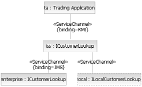
One key element to note here is that the LocalCustomerLookupProvider is a generated service, it is a thin wrapper service around a database query, there is a single operation representing a SQL select. This approach was chosen over direct access to the database by the in-store customer lookup service to allow for the local service to include additional business rules or even to become a more complete service at some later date.
However, this diagram only shows the structure of the collaboration, the following interaction diagram (UML 2.0 Sequence Diagram) represents the actual communications between the services. Note that we have added the operation getCustomerByPhone to the service specification. Also note that UML 2.0 allows for the specification of optional "fragment" of a sequence diagram, in this case denoting that we only communicate with the enterprise service if the local lookup fails.
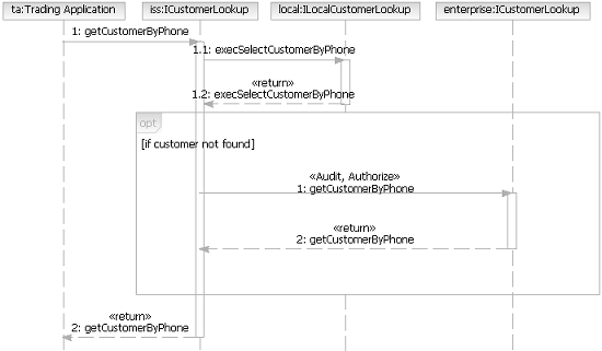
The combination of static structure and communication diagrams allow us to document the service composition and collaboration and have in this case only identified the need for a single operation on the service specification.
For more information see the activity Service Identification.Taking the model from the Service Identification activity we transition the identification of a set of candidate services into the detailed design of the services we intend to build. The first step is to map out the service specifications that realize the specifications above; as you can imagine there are decisions to be made in how services realize the service specifications from the model above. In this example we have a reasonably simple structure, but one that will probably be common to a lot of projects. In this case we have a single Service Providers presenting a single service which is the realization of a single specification. It is certainly possible to have more than one service per provider. We have also note some usage relationships between the services in this model, these dependencies are important in understanding how services can be evolved over time.
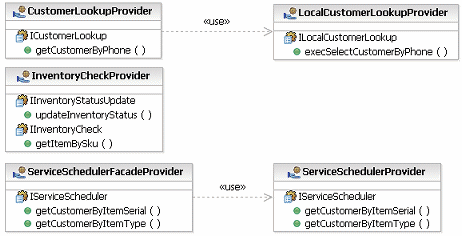
This structure allows us now to move more into the space of distribution, while the model is still a logical view of the services, as the service providers represent the units of deployment for the service model. The service providers are also required for the definition of composite services as a service itself (a UML 2.0 Port) is not able to own the structure required to describe the composition.
We said nothing above, in the service identification activity, about the actual messages exchanged between the operations described on the service specifications. This can be quite a common approach, to capture the responsibilities of the services in terms of operations deferring the detailed design of the messages until later - in some cases this approach is reversed, where the message structures are known ahead of time and then aggregated into a set of operations.
In this case we are able to leverage a domain model developed as a part of the component analysis model (previous developed asset) and so our message model is not built from nothing but identifies a subset of the domain model to be reused. The example below demonstrates this relationship, the domain classes are completely technology and platform unaware, our messages on the other hand are assumed to be data transfer objects, structures passed between services. So rather than changing the domain model we create the messages on the "outside" of the class structure, composed of elements in the inside.
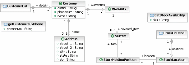
In this case we will focus on the realization of the in-store customer lookup service; this service is typical in the transformation from service model to design model. The transformation itself is documented in a guideline, and results in the following model structure.
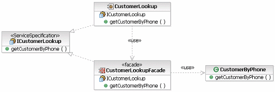
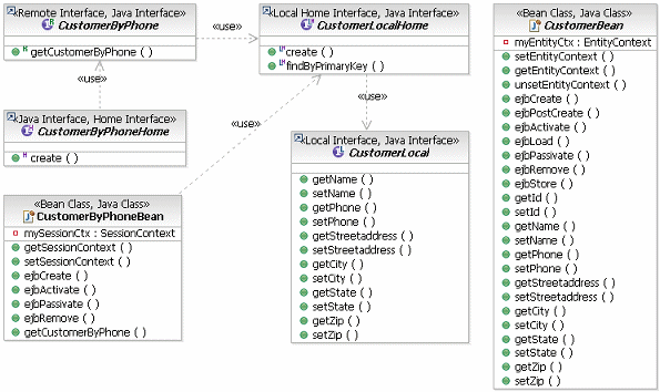
While this is still a design model we can, using tools, transform this model still further into the EJB implementation shown below. Basically this implementation is transformed from the CustomerByPhone class above and the messages detailing the customer are transformed into the entity bean used to query the database.
For more information see the guideline Going from Services to Service Components.