|
Document Subsystem Origin
During Task: Functional Area Analysis we identified a set of subsystems that
corresponded to the input received from a Component Business Map (see Concept: Component Business Modeling). During Process Decomposition, the identified
leaf-level activity nodes (Concept: Business Process Decomposition) may be placed on the subsystems as the
operations or services that the subsystem, as a facade, will provide. The functionality of these operations will be
realized by the service component's functional components. Also, you may choose to group these operations onto
interfaces that are offered by the subsystem. The operation non-functional requirements will be used to mine out
the technical components and services required within the subsystem.
It is important that the relationship between these identified subsystems and their original source be kept
in-place. In cases where both the business-level and service model work products are in UML, the dependency information
may easily be stored in the models; otherwise, such information should be stored in the Template: Service Model in Word or held in an associated work product.
ISV Considerations: Services may be realized through existing subsystems such as custom applications, software
packages and/or Independent Software Vendors. As the following section explains, in some cases, identification of new
subsystems may involve physical grouping of services based on criteria such as data affinity, cost, performance etc.,
although subsystem identification is usually done top-down during Functional Area Analysis activity. The allocation of
the components to the architectural tiers, in order to satisfy architectural constraints imposed by non-functional
requirements, is explained in Service Realization.
Example
The output from the functional area analysis for an example rental agency was the following table:
|
Domain
|
Functional Area
|
Subsystem
|
Description
|
|
Marketing and Customer Management
|
Customer Service
|
Customer Service
|
Provides all automated functions for the functional area.
|
|
Products
|
Promotions Management
|
Promotions Management
|
Provides all automated functions for the functional area.
|
|
Rental Fleet Logistics
|
Fleet Management
|
Fleet Management
|
Provides all automated functions for the functional area.
|
|
Rentals Management
|
Rental
|
Rental
|
Provides all automated functions for the functional area.
|
|
Rentals Management
|
Reservations
|
Reservations
|
Provides all automated functions for the functional area.
|
|
Rentals Management
|
Pricing
|
Pricing
|
Provides all automated functions for the functional area.
|
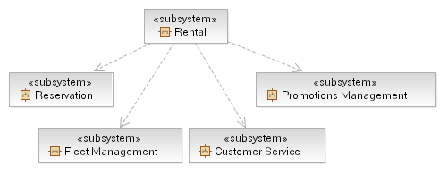
The resulting UML model of the subsystems identified above would be the following, note that the subsystem dependencies
are already provided in the model shown below.
For each subsystem either the details described by the Artifact: Design Subsystem should be documented, or may be
captured in the document-format service model (see Template: Service Model in Word), in a form similar to the following.
|
Name
|
Reservation
|
|
Description
|
The Reservation subsystem is used to create and manage car rental reservations.
|
|
Interfaces
|
-
Reserve Vehicle
-
Modify Reservation
-
Get Options Information
-
Confirm Rental Agreement
-
Locate Reservation
-
Cancel Reservation
|
|
Functions
|
-
Reserve Vehicle
-
Modify Reservation
-
Get Options Information
-
Confirm Rental Agreement
-
Locate Reservation
-
Cancel Reservation
|
|
Dependencies
|
None
|
|
Non-Functional Requirements
|
None
|
|
Identify and Apply Service Component Patterns
In the Guideline: Service Component Patterns we introduce not only the different kinds
of components that are commonly used to implement the subsystems identified during this task, but also a set
of patterns that allow for scalable and flexible implementations of these subsystems. The patterns, and of course
additional patterns exist - this is not a complete set - and may be specified as part of the architecture of a project.
Selection of, or customization of, a particular pattern will depend upon:
-
The Functional and Non-Functional Requirements of the solution and specific Subsystem.
-
The Capabilities and Qualities of Service provided by any middleware upon which the components will be deployed.
-
The cost/complexity and benefit trade-off between different patterns.
|
Identify Service Component
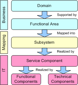
Subsystems, in and of themselves, are not IT assets and not deployable into the IT infrastructure; they provide a
bridge between the business and IT perspectives. Each subsystem is realized by one or more Service Components where
a Service Component is an enterprise-scale asset (a managed software element with guaranteed availability, load
balancing, security, performance, and versioning). The Service Component is in turn realized by multiple Functional and
Technical Components according to the diagram below.
Generally each service assigned to a Subsystem will result in a Service Component; Functional and Technical Components
may be shared between Service Components within the same subsystem.
|
Identify Functional Components
Functional components provide additional business function to a service component; in many respects, the capability
provided by a service component is dependent entirely on its functional components and any additional business logic it
implements on top of these.
Functional components are often to be found among Type Managers - components that manage a particular domain element,
for example "Vehicle", "Customer", "Schedule", and so forth. It should be made clear that these domain elements are
more frequently large-grained graphs of data rather than simple structures.
Example
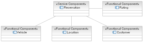
Considering the Rent-a-Car example, the Reservation service component need to be able to pull together details about
the customer, the location they wish to hire from and the vehicles available for the class they specify. Also we need
to be able to determine the customer's rating such that we can provide the correct level of service in the event of
issues such as unavailable vehicles. The following diagram demonstrates the component model for Reservation.
|
Identify Technical Components
Technical, or Infrastructure, components serve to make available horizontal platform capabilities; that is the
capabilities they provide are not specific to the business domain but cut across business domains. These technical
services are frequently provided by middleware products including operating systems and are used either directly by the
service component or by the functional components on which they rely.
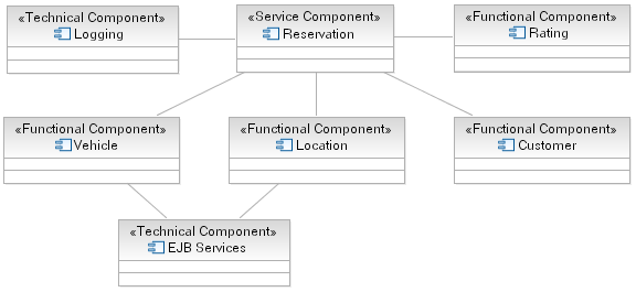
Example
In completing the Rent-a-Car component model (see functional component step above) we include two technical components
into the model, one for the Reservation to log the completion of a reservation request and one to denote that the
Vehicle and Location components rely on EJB Services to persist their business data.
Alternatively you can use a tabular format in expressing the required components and their relationship to the services
previously identified, as shown in the figure below.
|
Distribute Subsystem Behavior to Subsystem Elements
|
Purpose
|
To specify the internal behavior of the subsystem.
To identify new design classes or design subsystems needed to satisfy subsystem
behavioral requirements.
|
The external behavior of a subsystem is primarily defined by the interfaces it realizes. When a subsystem realizes an
interface, it makes a commitment to support each and every operation defined by the interface. The operation may be in
turn realized by an operation on a design element (i.e., Design Class or Design Subsystem) contained by the subsystem; this operation may
require collaboration with other design elements
The collaborations of model elements within the subsystem should be documented using sequence diagrams which show how
the subsystem behavior is realized. Each operation on an interface realized by the subsystem should have one or more
documenting sequence diagrams. This diagram is owned by the subsystem, and is used to design the internal
behavior of the subsystem.
If the behavior of the subsystem is highly state-dependent and represents one or more threads of control, state
machines are typically more useful in describing the behavior of the subsystem. State machines in this context are
typically used in conjunction with active classes to represent a decomposition of the threads of control of the system
(or subsystem in this case), and are described in statechart diagrams, see Guideline: Statechart Diagram. In real-time systems, the behavior of Artifact: Capsules will also be described using state machines.Within the subsystem, there may
be independent threads of execution, represented by active classes.
In real-time systems, Artifact: Capsules will be used to encapsulate these threads.
Example:
The collaboration of subsystems to perform some required behavior of the system can be expressed using sequence
diagrams:
This diagram shows how the interfaces of the subsystems are used to perform a scenario. Specifically, for the Network
Handling subsystem, we see the specific interfaces (ICoordinator in this case) and operations the subsystem must
support. We also see the NetworkHandling subsystems is dependent on the IBHandler and IAHandler interfaces.
Looking inside the Subsystem, we see how the ICoordinator interface is realized:
The Coordinator class acts as a "proxy" for the ICoordinator interface, handling the interface operations and
coordinating the interface behavior.
This "internal" sequence diagram shows exactly what classes provide the interface, what needs to happen internally to
provide the subsystem's functionality, and which classes send messages out from the subsystem. The diagram clarifies
the internal design, and is essential for subsystems with complex internal designs. It also enables the subsystem
behavior to be easily understood, hopefully rendering it reusable across contexts.
Creating these "interface realization" diagrams, it may be necessary to create new classes and subsystems to perform
the required behavior. The process is similar to that defined in Use Case Analysis, but instead of Use Cases we are
working with interface operations. For each interface operation, identify the classes (or in some cases where the
required behavior is complex, a contained subsystem) within the current subsystem which are needed to perform the
operation. Create new classes/subsystems where existing classes/subsystems cannot provide the required behavior (but
try to reuse first).
Creation of new design elements should force reconsideration of subsystem content and boundary. Be careful to avoid
having effectively the same class in two different subsystems. Existence of such a class implies that the subsystem
boundaries may not be well-drawn. Periodically revisit Task: Identify Design Elements to re-balance subsystem responsibilities.
It is sometimes useful to create two separate internal models of the subsystem - a specification targeted to the
subsystem client and a realization targeted to the implementers. The specification may include "ideal" classes and
collaborations to describe the behavior of the subsystem in terms of ideal classes and collaborations. The realization,
on the other hand, corresponds more closely to the implementation, and may evolve to become the implementation.
For more information on Design Subsystem specification and realization, see Work Product Guideline: Design Subsystem, Subsystem Specification and Realization.
|
Document Subsystem Elements
|
Purpose
|
To document the internal structure of the subsystem.
|
To document the internal structure of the subsystem, create one or more class diagrams showing the elements contained
by the subsystem, and their associations with one another. One class diagram should be sufficient, but more can be used
to reduce complexity and improve readability.
An example class diagram is shown below:
Example Class Diagram for an Order-Entry System.
Modeled as a component, the internal content of a subsystem can be alternatively represented within the component
rectangle in a component diagram. This representation also allows us to include the interaction points of this
subsystem to other parts of the system, which is done through its interfaces.
An example of component diagram is shown below, depicting the Order subsystem, its internal content, as well as its
provided and required interfaces.
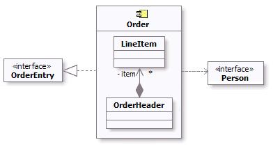
Example component diagram for Order Subsystem
As a component is a structured class, it can be tightly encapsulated by forcing communications from
outside to pass through ports obeying declared interfaces, which brings additional precision in specification and
interconnection for that component. This representation allows us to "wire" instances of parts through connectors to
play a specific role in the component implementation (refer to Concept: Structured Class for additional information).
An example of composite structure diagram for the Order subsystem using interfaces and ports is shown below.
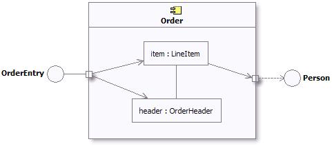
Example composite structure diagram for Order Subsystem
In addition, a statechart diagram may be needed to document the possible states the subsystem can assume, see Guideline: Statechart Diagram.
The description of the classes contained in the subsystem itself is handled in the Task: Class Design.
|
Describe Subsystem Dependencies
|
Purpose
|
To document the interfaces upon which the subsystem is dependent.
|
When an element contained by a subsystem uses some behavior of an element contained by another subsystem, a dependency
is created between the enclosing subsystems. To improve reuse and reduce maintenance dependencies, we want to express
this in terms of a dependency on a particular Interface
of the subsystem, not upon the subsystem itself nor on the element contained in the subsystem.
The reason for this is two-fold:
-
We want to be able to substitute one model element (including subsystems) for one another as long as they offer the
same behavior. We specify the required behavior in terms of interfaces, so any behavioral requirements one model
element has on another should be expressed in terms of interfaces.
-
We want to allow the designer total freedom in designing the internal behavior of the subsystem so long as
it provides the correct external behavior. If a model element in one subsystem references a model element in
another subsystem, the designer is no longer free to remove that model element or redistribute the behavior of that
model element to other elements. As a result, the system is more brittle.
In creating dependencies, ensure that there are no direct dependencies or associations between model elements contained
by the subsystem and model elements contained by other subsystems. Also ensure that there are no circular dependencies
between subsystems and interfaces; a subsystem cannot both realize an interface and be dependent on it as well.
Dependencies between subsystems, and between subsystems and packages, can be drawn directly as shown below. When shown
this way, the dependency states that one subsystem (Invoice Management, for example) is directly dependent on another
subsystem (Payment Scheduling Management).
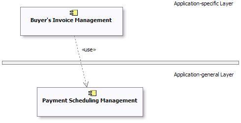
Example of Subsystem Layering using direct dependencies
When there is a potential for substitution of one subsystem for another (where they have the same interfaces), the
dependency can be drawn to an Interface realized by the subsystem, rather than to the subsystem
itself. This allows any other model element (subsystem or class) which realizes the same interface to be used. Using
interface dependencies allows flexible frameworks to be designed using replaceable design elements.
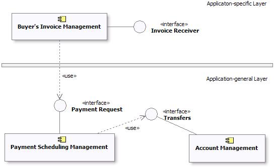
Example of Subsystem Layering using Interface dependencies
|
|
