|
Subsystems can be used in a
number of complementary ways, to partition the system into units which
-
can be independently ordered, configured, or delivered
-
can be independently developed, as long as the interfaces remain unchanged
-
can be independently deployed across a set of distributed computational nodes
-
can be independently changed without breaking other parts of the systems
Thus, subsystems are ideal for modeling components - the replaceable units of assembly in component-based development -
that are larger than a single design class.
In addition, subsystems can
-
partition the system into units which can provide restricted security over key resources
-
represent existing products or external systems in the design.
A complex analysis class is mapped to a design subsystem if it appears to embody behavior that cannot be the
responsibility of a single design class acting alone. A complex design class may also become a subsystem, if it is
likely to be implemented as a set of collaborating classes.
Subsystems are also a good means of identifying parts of the system that are to be developed independently by a
separate team. If the collaborating design elements can be completely contained within a package along with their
collaborations, a subsystem can provide a stronger form of encapsulation than that provided by a simple package. The
contents and collaborations within a subsystem are completely isolated behind one or more interfaces, so that the
client of the subsystem is only dependent upon the interface. The designer of the subsystem is then completely isolated
from external dependencies; the designer (or design team) is required to specify how the interface is realized, but
they are completely free to change the internal subsystem design without affecting external dependencies. In large
systems with largely independent teams, this degree of de-coupling combined with the architectural enforcement provided
by formal interfaces is a strong argument for the choice of subsystems over simple packages.
The design subsystem is used to encapsulate these collaborations in such a way that clients of the subsystem can be
completely unaware of the internal design of the subsystem, even as they use the services provided by the subsystem. If
the participating classes/subsystems in a collaboration interact only with each other to produce a well-defined set of
results, the collaboration and its collaborating design elements should be encapsulated within a subsystem.
This rule can be applied to subsets of collaborations as well. Anywhere part or all of a collaboration can be
encapsulated and simplified, doing so will make the design easier to understand.
Hints
Hint
|
Details
|
|
Look for optionality
|
If a particular collaboration (or sub-collaboration) represents optional behavior, enclose it in a
subsystem. Features which may be removed, upgraded, or replaced with alternatives should be considered
independent.
|
|
Look to the user interface of the system.
|
If the user interface is relatively independent of the entity classes in the system (i.e. the two can
and will change independently), create subsystems which are horizontally integrated: group related user
interface boundary classes together in a subsystem, and group related entity classes together in
another subsystem.
|
|
If the user interface and the entity classes it displays are tightly coupled (i.e. a change in one
triggers a change in the other), create subsystems which are vertically integrated: enclose related
boundary and entity classes in common subsystem.
|
|
Look to the Actors
|
Separate functionality used by two different actors, since each actor may independently change their
requirements on the system.
|
|
Create subsystems to encapsulate access to an external system or device.
|
|
Look for coupling and cohesion between design elements
|
Highly coupled or cohesive classes/subsystems collaborate to provide some set of services. Organize
highly coupled elements into subsystems, and separate elements along lines of weak coupling. In some
cases, weak coupling can be eliminated entirely by splitting classes into smaller classes with more
cohesive responsibilities, or repartitioning subsystems appropriately.
|
|
Look at substitution
|
If there are several levels of service specified for a particular capability (example: high, medium and
low availability), represent each service level as a separate subsystem, each of which will realize the
same set of interfaces. By doing so, the subsystems are substitutable for one another.
|
|
Look at distribution
|
Although
there can be multiple instances of a particular subsystem, each executing on different nodes, in many
architectures it is not possible for a single instance of a component to be split across nodes. In the
cases where subsystem behavior must be split across nodes, it is recommended that you decompose the
subsystem into smaller subsystems (each representing a single component) with more restricted
functionality.
Determine the functionality that must reside upon each node and create a new subsystem to 'own' that
functionality, distributing the responsibilities and related elements of the original subsystem
appropriately.
The new subsystems are internal to the original subsystem.
|
Once the design has been organized into subsystems, update the use-case realizations accordingly.
Design Subsystems are modeled using UML components. This construct provides the following modeling capabilities:
-
can group classes to define a larger granularity part of a system
-
can separate the visible interfaces from internal implementation
-
can have execution at run-time
Some other considerations are:
-
Each Design Subsystem must be given a name and a short description.
-
The responsibilities of the original analysis class should be transferred to the newly-created subsystem, using the
description of the subsystem to document the responsibilities
Note: UML 2.0 also defines a stereotype for component named <<subsystem>>, indicating that this may be
used, for example, to represent large scale structures. A RUP Design Subsystem may or may not be a large scale
structure; both are Design Subsystems from the RUP perspective. This is an issue for the software architect to decide
(whether to choose for example to label components that are composed of components as <<subsystem>>).
Where an existing product is one that exports interfaces, i.e. operations (and perhaps receptions), but otherwise keeps all details of implementation hidden, then
it may be modeled as a subsystem in the logical view. Examples of products the system uses that you may be able
to represent by a subsystem include:
-
Communication software (middleware).
-
Database access support (RDBMS mapping support).
-
Application-specific products.
Some existing products such as collections of types and data structures (e.g. stacks, lists, queues) may be better
represented as packages, because they reveal more than behavior, and it is the particular contents of the package that
are important and useful and not the package itself, which is simply a container.
Common utilities, such as math libraries, could be represented as subsystems, if they simply export interfaces, but
whether this is necessary or makes sense depends on the designer's judgment about the nature of the thing
modeled. Subsystems are object-oriented constructs (as they are modeled components): a subsystem can have
instances (if the designer so indicates). UML provides another way to model groups of global variables and procedures
in the utility, which is a stereotype of class - the utility has no instances.
When defining the subsystem to represent the product, also define one or more interfaces to represent the product
interfaces.
Design Subsystems (modeled as UML components) differ from packages in their semantics: a subsystem provides behavior
through one or more interfaces which it realizes. Packages provide no behavior; they are simply containers of things
which provide behavior.
The reason for using a subsystem instead of a package is that subsystems encapsulate their contents, providing behavior
only through their interfaces. The benefit of this is that, unlike a package, the contents and internal behaviors of a
subsystem can be changed with complete freedom so long as the subsystem's interfaces remain constant. Subsystems also
provide a 'replaceable design' element: any two <<realization>> components that realize the same interfaces
(or <<specification>> component) are interchangeable.
In order to ensure that subsystems are replaceable elements in the model, a few rules need to be enforced:
-
A subsystem should minimize exposing of its contents. Ideally no element contained by a subsystem should have
'public' visibility, and thus no element outside the subsystem depends on the existence of a particular element
inside the subsystem. Some exceptions are as follows:
-
In some technologies, the externals of a subsystem cannot be modeled as a UML interface. For example, a
Java interface is modeled as a stereotyped class.
-
The subsystem design may require exposing classes rather than UML interfaces. For example, a "delegate" or
"access" class can be used to hide a complex collaboration of other classes. While an ordinary package
could be used instead, a subsystem could be used in order to emphasize the intent to encapsulate behavior
and hide internal details.
-
When a subsystem's externals are not UML interfaces, it is often helpful to have a diagram (for example named
"External View") that shows the visible elements of the subsystem.
-
A subsystem should define its dependencies on subsystem interfaces (and publicly visible elements of subsystem in
the exceptional cases described above). In addition, a number of subsystems may share a set of interfaces or class
definitions in common, in which case those subsystems 'import' the contents of the packages which contain the
common elements. This is more common with packages in lower layers in the architecture, to ensure that common
definitions of classes which must pass between subsystems are consistently defined.
An example of Subsystem and Package dependencies is shown below:
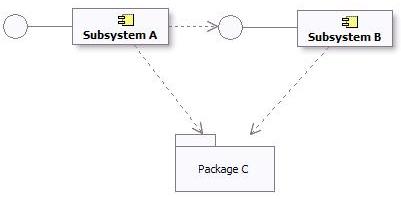
Subsystem and Package Dependencies in the Design Model
The UML ([UML04]) states:
A number of UML standard stereotypes exist that apply to component, e.g. <<specification>> and
<<realization>> to model components with distinct specification and realization definitions, where one
specification may have multiple realizations.
A Component stereotyped by <<specification>> specifies a domain of objects without defining the
physical implementation of those objects. It will only have provided and required interfaces, and is not intended
to have any realizing classes and sub components as part of its definition.
A Component stereotyped by <<realization>> specifies a domain of objects and that also defines the
physical implementation of those objects. For example, a Component stereotyped by <<realization>> will
only have realizing classes and sub components that implement behavior specified by a separate
<<specification>> Component.
The separation of specification and realization essentially allows for two separate descriptions of the subsystem. The
specification serves as a contract that defines everything that a client needs to know to use the subsystem. The
realization is the detailed internal design intended to guide the implementer. If you wish to support multiple
realizations, create separate "realization" subsystems, and draw a realization from each realization subsystem to the
specification subsystem.
If the internal state and behavior of the subsystem is relatively simple, it may be sufficient to specify the subsystem
by its exposed interfaces, state diagrams to describe the behavior, and descriptive text.
For more complex internal state and behavior, analysis classes can be used to specify the subsystem at a high level of
abstraction. For large systems of systems, the specification of a subsystem may also include use cases. See Developing Large-Scale Systems with the Rational Unified Process.
Providing a detailed specification separate from the realization tends to be most useful in the following situations:
-
the subsystem realization's internal state or behavior is complex - and the specification needs to be expressed as
simply as possible in order for clients to use it effectively;
-
the subsystem is a reusable "assembly component" intended for assembly into a number of systems (see Concept: Component);
-
the subsystem's internals are expected to be developed by a separate organization;
-
multiple implementations of the subsystem need to be created;
-
the subsystem is expected to be replaced with another version that has significant internal changes without changes
to the externally visible behavior.
Maintaining a separate specification takes effort, however - as one must ensure that the realization of the subsystem
is compliant with the specification. The criteria for when and if to create separate specification and realization
classes and collaborations should be defined in Work Product: Project Specific Guidelines.
A specification should define its dependencies. These are the interfaces and visible elements from other subsystems and
packages that must be available in all compliant realizations of the subsystem.
A realization may have additional dependencies, introduced by the designer or implementer. For example, there may be an
opportunity to use a utility component to simplify the implementation - but the use of this utility component is a
detail that need not be exposed to clients. These additional dependencies should be captured on a separate diagram as
part of the realization.
A fully detailed specification defines everything a client needs to use the subsystem. This means refining the exposed
interfaces and any publicly visible elements so that they are one-to-one with code. Analysis classes introduced to
specify the subsystem behavior should remain as high level abstractions, since they are intended to be independent of
any subsystems realizations.
The realization elements of a subsystem should align closely to the code.
See Concept: Mapping from Design to Code for some further discussion on this topic.
Modeling
Design subsystems may be modeled as either UML 2.0 components or UML 1.5 subsystems. These constructs provide almost
equivalent modeling capabilities like modularity, encapsulation, and instances able to execute at run-time.
Some additional considerations about these modeling options are:
-
UML 1.5 subsystems explicitly included the notion of "specification" and "realization" (defined above in the
section titled Subsystem Specification and
Realization). The UML 2.0 components support the notion of specification (in the form of one or more provided
and required interfaces) and realization (internal implementation consisting of one or more classes and sub
components that realize its behavior).
-
UML 1.5 subsystems were also packages. UML 2.0 components have packaging capabilities, which means they may own and
import a potentially large set of model elements.
However, by and large, these notations can be used interchangeably. Whether to represent Design Subsystems as UML 1.5
subsystems or UML 2.0 components is a decision that should be documented in the Project-Specific Guidelines tailored for your project.
If your visual modeling tool supports UML 1.5 packages but not UML 1.5 subsystems, a package stereotyped as
<<subsystem>> can be used to denote a subsystem.
Subsystem Dependency Restrictions
The same dependency restrictions and discussions mentioned in the section titled Subsystem Dependency Restrictions also apply for design subsystems
being modeled as UML 1.5 subsystems.
An example of Subsystem and Package dependencies in UML 1.5 is shown below:
Subsystem and Package Dependencies in the Design Model
Subsystem Specification and Realization
The UML 1.5 stated:
The contents of a subsystem are divided into two subsets: 1) specification elements and 2) realization elements.
The specification elements, together with the operations and receptions of the subsystem, are used for giving an
abstract specification of the behavior offered by the realization elements. The collection of realization elements
model the interior of the behavioral unit of the physical system.
The separation of specification and realization essentially allows for two separate descriptions of the subsystem. The
specification serves as a contract that defines everything that a client needs to know to use the subsystem. The
realization is the detailed internal design intended to guide the implementer.
One option for modeling specifications and realizations, if not directly supported by the modeling environment, is to
place two packages, specification and realization, inside each subsystem.
One motivation for specifications is to support multiple realizations. This was not directly supported in the UML 1.x.
If you wish to support multiple realizations using UML 1.5 subsystems, create separate "realization" subsystems, and
draw a realization from each realization subsystem to the specification subsystem.
Basically, the same considerations for Specification and Realization that apply for UML 2.0, also apply here (see When and How to Use, Dependencies, and Relationship to Implementation for explanation).
Additional Information
Refer to Differences Between UML 1.x and UML 2.0 for more information.
|
